Final Project: Smart Pillbox
Completed Project
For my PS70 final project, I created The Smart Pillbox! This pillbox is designed to simplify your medication routine with smart reminders and day indicators. My demo model caters to two days, with plans to expand to a full week.

Click below to watch my product demo video!
Motivation
The genesis of the Smart Pillbox project stems from a personal experience. My grandmother, like many seniors, faces the daunting task of managing multiple medications daily. Observing her struggles, I noticed how easily she could forget to take her pills, leading to potential health risks and anxiety about maintaining her medication schedule. This is not just her challenge but a common issue faced by millions worldwide, particularly the elderly who often deal with complex medication regimens. The need for a simple, intuitive solution became apparent. It inspired me to create a device that not only reminds users to take their medication but also organizes it in a way that's easy to understand and follow. The Smart Pillbox project is more than just a technological endeavor; it's a personal mission to enhance the quality of life for my grandmother and others facing similar challenges.
How to Use
The Smart Pillbox is designed for ease of use, ensuring anyone can benefit from its features without any hassle. Here's how it works:
Loading Medication
Open the pillbox and place your medications in the designated compartments. Each compartment is labeled for a specific day, allowing you to organize your pills accordingly.
Automatic Reminders
The pillbox is equipped with an external light that automatically turns on at two critical times: midnight and 5pm. The first light will be on when you wake up, as a reminder to take morning medications and the next light will turn on when you’re winding down, as a reminder to take night time medications.
Acknowledging Medication Intake
Once you open the pillbox in response to the reminder light, the light will automatically turn off. This feature confirms that you have accessed your medications, effectively acknowledging your medication intake.
Day Indicators
Inside the pillbox, each compartment has a light indicator. These indicators help you track what day of the week it is, ensuring you're taking the correct medication for the right day. In this demo version, there are indicators for two days, with each day distinctly marked.
Hardware
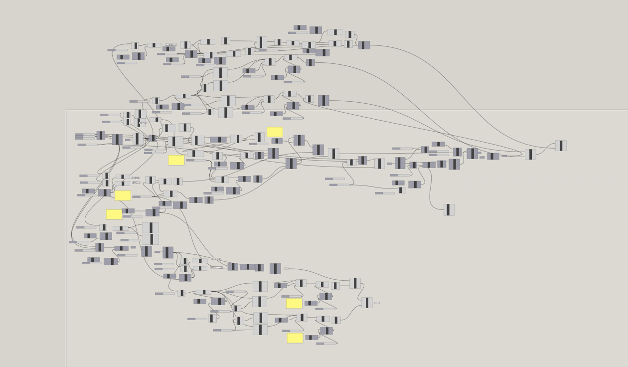
Download the Grasshopper File (.gh)
Download the Rhino CAD File (.3dm)
The pillbox was designed using Rhino and Grasshopper and was constructed using 3D printing technology, comprising two main parts: the top and the bottom.
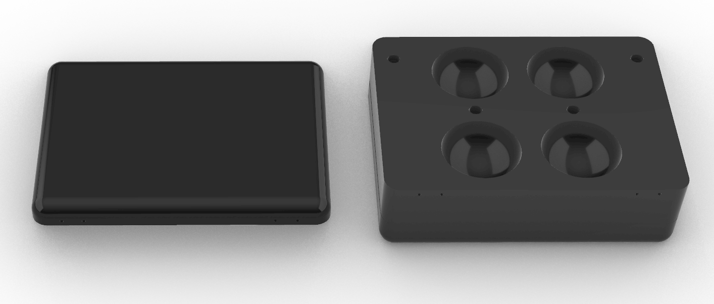
Top Part
The top part of the box is designed with holes to accommodate magnets. These magnets play a crucial role in the functioning of the device, as they interact with a hall effect sensor located in the bottom part of the box.
Bottom Part
The bottom part of the pillbox is more intricate. It features four spherical indents, each serving as a compartment for medication storage. These compartments are aligned with their respective days, and each is equipped with an LED light indicator. On the same surface, a hall effect sensor is placed to match up with the magnets on the top piece when the box is closed. Additionally, the front of the pillbox includes an external light. All of these sensors are housed in bigger tubes that taper into smaller tubes that extend beneath the box, concealing the wires and ensuring that the sensors don’t fall through their holes.
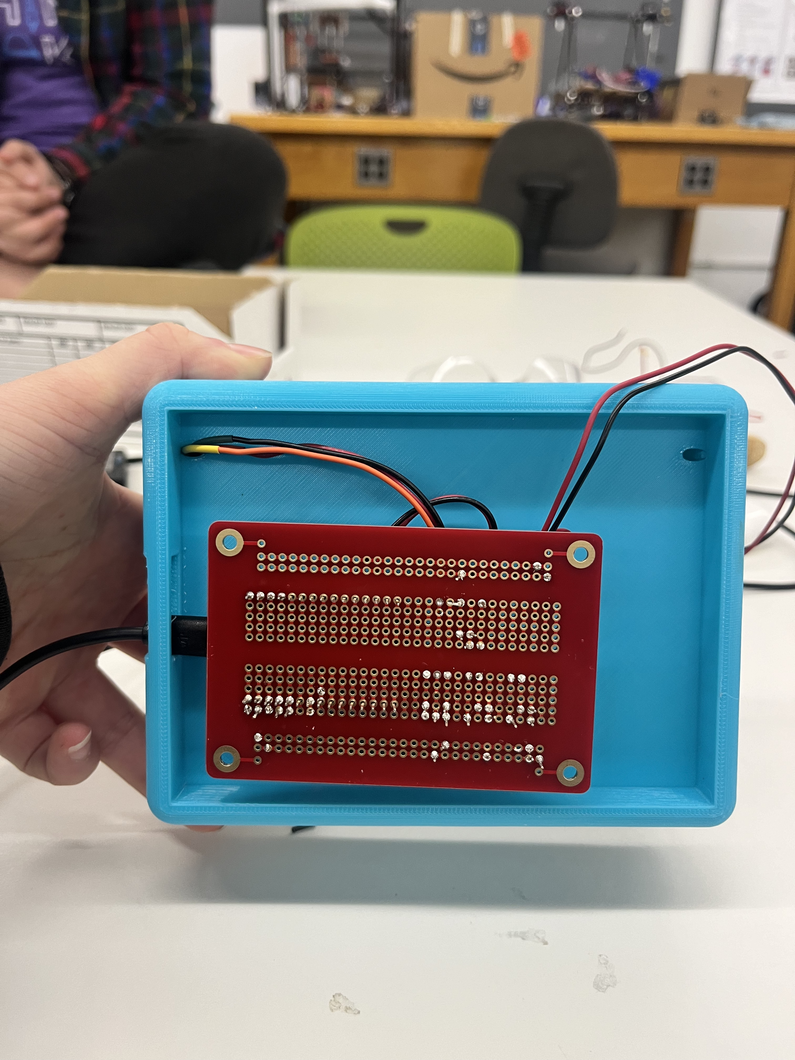
Underneath the box, there's a compartment specifically designed to house the ESP32 board. This compartment ensures that the board is securely positioned and integrated with the other components, forming the heart of the Smart Pillbox's electronic functionality. The wires from all the sensors feed down into this compartment to connect to the ESP32. All of the circuitry has been soldered onto a solderable breadboard to ensure consistent usage.
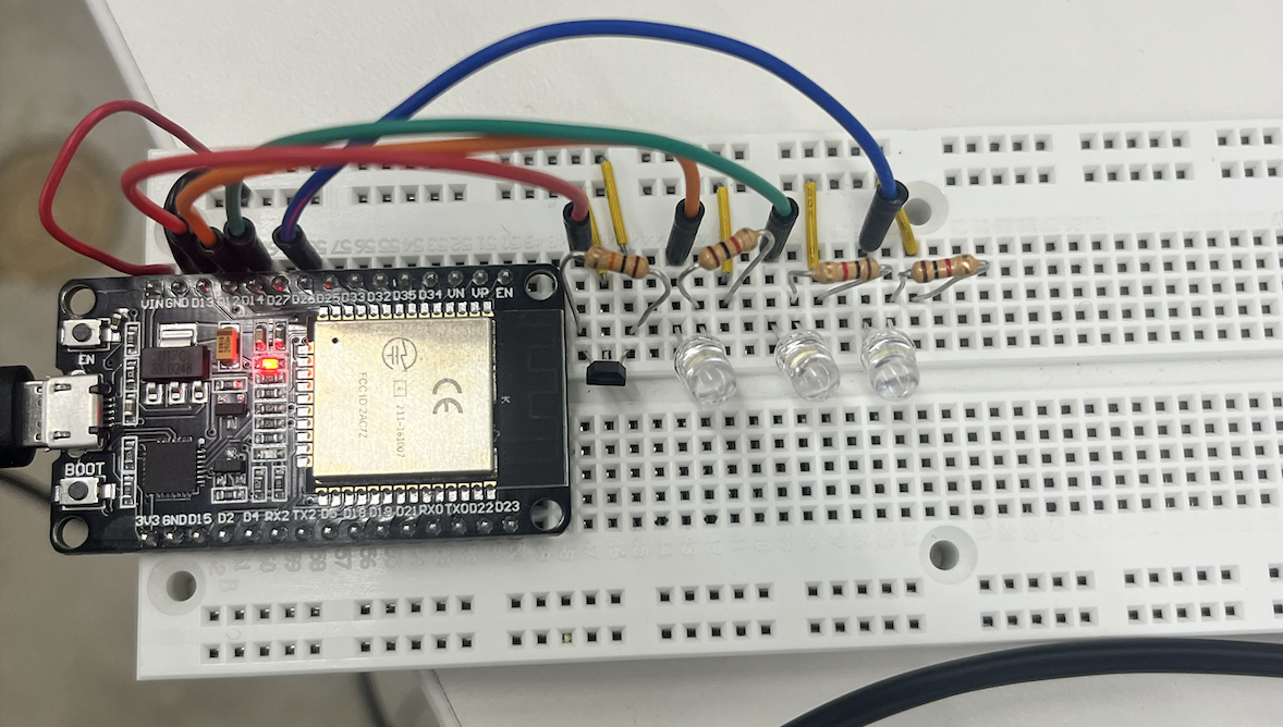
Circuitry
The circuitry forms the backbone of the Smart Pillbox's functionality. The system includes three LEDs, wired with 1kΩ resistors. One of these LEDs is the outside indicator light and the other two lights serve as the indicators of the day. Alongside the LEDs, I've wired a digital hall effect sensor. This sensor is connected with a 10kΩ resistor.
Software
I developed two versions of code to ensure both testing flexibility and real-world functionality.
Test Code Version
The first version is a test code designed to allow users to manually input the time and day of the week. This interactive feature is particularly useful for demonstrating and observing the pillbox's reactions in a controlled environment. In this test mode, time is accelerated, with each second representing an hour. This allows for a rapid and clear demonstration of how the pillbox's lights and sensors respond to the passing of time and the opening and closing of the box.
Download the Test CodeFinal Code Version
The second version is the final, fully-functional code. This iteration utilizes a connection to a Network Time Protocol (NTP) server, ensuring accurate and real-time updates for the current time and day of the week. NTP is a networking protocol designed to synchronize clocks over a computer network. In the context of the Smart Pillbox, the ESP32 board connects to an NTP server, which provides precise time information. This enables the pillbox to autonomously determine the correct times to activate or deactivate the reminder lights based on the actual time of day. The implementation of NTP server interaction in the ESP32 was greatly aided by resources such as the tutorial found at randomnerdtutorials.com, which provided valuable insights into managing time synchronization.
By integrating the NTP server, the Smart Pillbox aligns its functions with the actual time, ensuring that the medication reminders are accurate and reliable. This approach eliminates the need for manual time setting, making the device more user-friendly and efficient, especially for users who may not be as comfortable with technology.
Download the Final Code#include <WiFi.h>
#include "time.h"
const char* ssid = *****
const char* password = *****
const char* ntpServer = "pool.ntp.org";
const long gmtOffset_sec = -18000; // offset -4 hours
const int daylightOffset_sec = 3600;
int hall_pin = 13;
int box_led_pin = 26;
int saturday_led_pin = 12;
int sunday_led_pin = 14;
bool boxOpened = false;
void setup() {
pinMode(hall_pin, INPUT);
pinMode(box_led_pin, OUTPUT);
pinMode(saturday_led_pin, OUTPUT);
pinMode(sunday_led_pin, OUTPUT);
Serial.begin(9600);
// Connect to Wi-Fi
WiFi.begin(ssid, password);
while (WiFi.status() != WL_CONNECTED) {
delay(500);
Serial.print(".");
}
Serial.println("
WiFi connected.");
// Init and get the time
configTime(gmtOffset_sec, daylightOffset_sec, ntpServer);
}
void loop() {
delay(1000);
checkTimeAndControlLight();
readHallSensor();
controlDayLed();
}
void checkTimeAndControlLight() {
struct tm timeinfo;
if (!getLocalTime(&timeinfo)) {
Serial.println("Failed to obtain time");
return;
}
// Control light based on time
if ((timeinfo.tm_hour == 0 && timeinfo.tm_min == 0) ||
(timeinfo.tm_hour == 17 && timeinfo.tm_min == 0)) {
if (!boxOpened) {
digitalWrite(box_led_pin, HIGH);
}
} else {
boxOpened = false;
}
}
void readHallSensor() {
int pinValue = digitalRead(hall_pin);
if (pinValue == LOW) {
digitalWrite(box_led_pin, LOW);
boxOpened = true;
}
}
void controlDayLed() {
struct tm timeinfo;
if (!getLocalTime(&timeinfo)) {
Serial.println("Failed to obtain time");
return;
}
// Control Saturday and Sunday LEDs
digitalWrite(saturday_led_pin, (timeinfo.tm_wday == 6) ? HIGH : LOW); // 6 is Saturday
digitalWrite(sunday_led_pin, (timeinfo.tm_wday == 0) ? HIGH : LOW); // 0 is Sunday
}
Creation Timeline
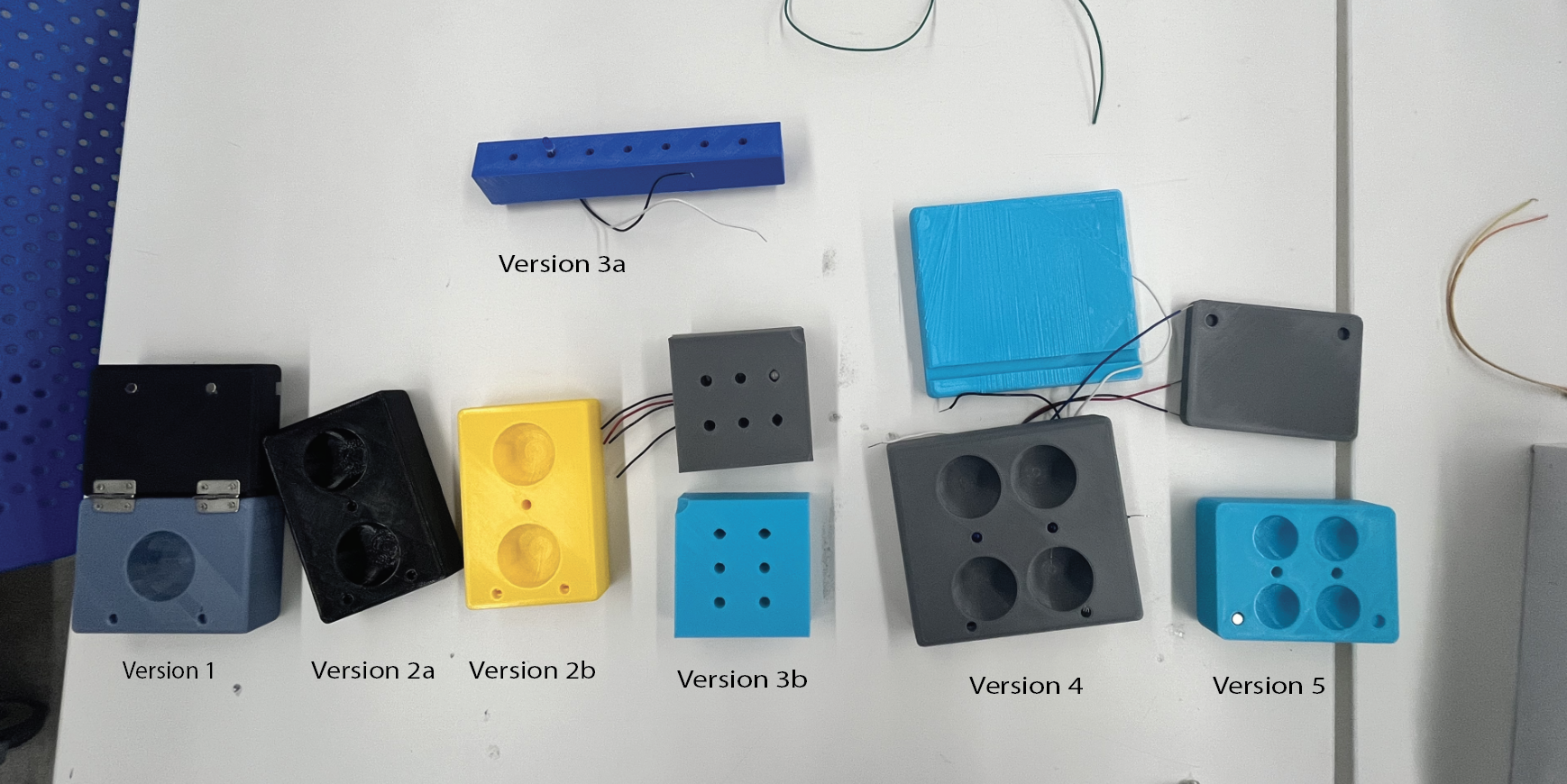
My journey in developing the Smart Pillbox has been marked by continuous challenges and successes, with each iteration bringing me a little closer to the final product. Here's an overview into the evolutionary stages of my project:
- Version 1: The inception began with a basic box featuring a spherical cutout and a hall effect sensor. The primary aim was to validate the functionality of the hall effect sensor.
- Versions 2a and 2b: These iterations introduced two spheres, with modifications in the magnet and LED hole sizes, as well as the wire tube dimensions. The focus was on testing the fit of the LED and magnets, along with exploring ways to conceal the wiring inside the box.
- Version 3a: This version featured a box with seven LED holes, specifically designed to test the Network Time Protocol (NTP) server code and the simultaneous control of seven LEDs.
- Version 3b: Focused on precision, this prototype involved printing twelve different hole sizes onto two wood blocks to determine the optimal fit for the LEDs and wires.
- Version 4: Scaling up to represent two days using four spheres, this model involved revisiting previous versions to adjust LED holes for shrink-wrapped wires, aiding in finalizing the dimensions of the product.
- Version 5: A significant redesign led to a more scalable model, accommodating any number of holes or days. The model was also made more compact to expedite the printing process.
Advanced Stages (Not Pictured)
- Version 6: Introduced a specialized pocket for the ESP32 and a cutout for charger connectivity, enhancing the practicality and usability of the device.
- Version 6.5: This iteration was focused on refining the design, particularly for the hinge holes. After multiple trials, the correct measurements were obtained. An attempt was made to incorporate an LED strip at the top, but challenges led to the exploration of alternative solutions for external indicator lights.
- Version 7: Further improvements included enlarging the ESP32 space for better durability, adding holes for hinges, and incorporating an external LED hole at the bottom for the indicator light, ensuring the pillbox could rest flat and function efficiently.
Circuitry
At the beginning of this project, I attempted to work on the physical box construction and the circuitry simultaneously. However, this approach made it challenging to debug the project when issues arose. To mitigate this, I decided to divide the project into two distinct phases: the physical components and the circuitry. This separation allowed me to focus on refining each aspect individually before integrating them into the final product.
While progressing through the various physical prototypes, I concurrently embarked on designing the circuit, ensuring its functionality in isolation. This involved soldering all LEDs and hall effect sensors onto longer wires, facilitating their integration within the box. After extending these wires, I conducted thorough tests to confirm their operational integrity.
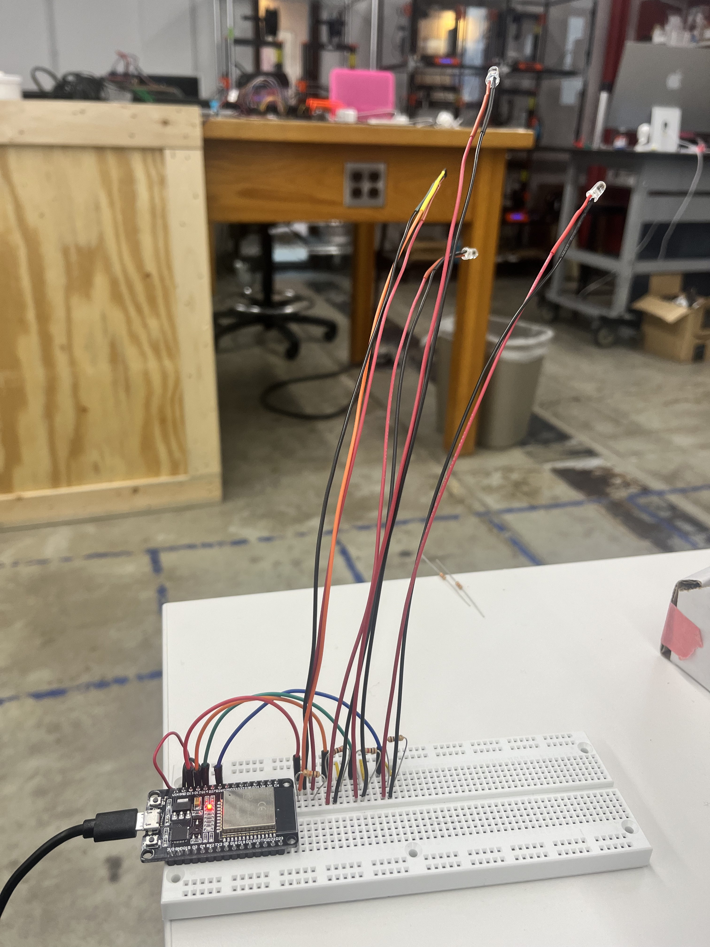
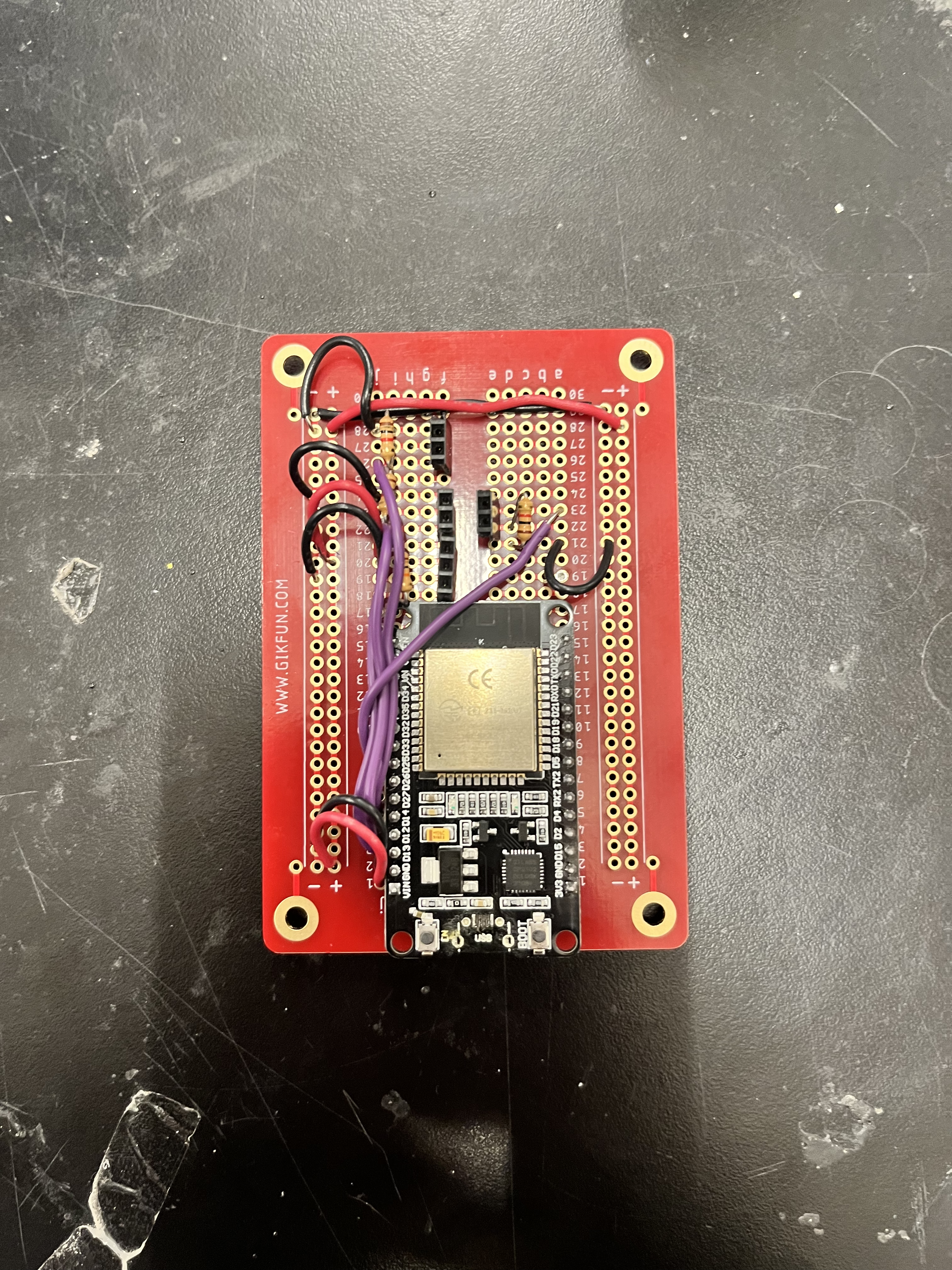
The final step in the circuitry phase involved soldering the ESP32 and all remaining connections onto a solderable breadboard. This measure was taken to overcome the issue of connections becoming loose during movement, a critical consideration for the pillbox’s practical use. This careful soldering process was vital to guarantee the reliability and durability of the electronic components, a cornerstone in the development of the Smart Pillbox.
Reflections
The journey in creating the Smart Pillbox was both incredibly challenging and immensely rewarding. It was a process filled with learning and growth, though not without its share of obstacles.
Throughout the project, there were so many moments where progress seemed elusive, where hours of work didn't quite translate into visible advancements. One of the frequent challenges I faced was the domino effect of changes; often, adjusting one component would inadvertently lead to issues in others, requiring constant tweaking and adaptation.
3D printing, while a cornerstone of this project, came with its own set of challenges, particularly due to the lengthy print times and the tendency of the 3d printers to stop working seemingly at random. Some prints took upwards of 14 hours, which made iterating and refining the design a slow and painstaking process.
This project, with all its ups and downs, has been a testament to the iterative nature of engineering and design. I'm particularly proud of how many skills I've developed in Rhino and Grasshopper. In the last few weeks of the semester, I completely redid my box design. Even though the product looked very simlar on the outside, my new model is much easier to work with and scale for future iterations. The second version of the box was not only much cleaner but also took almost 1/3 od the time it took me to make the original box. It was an awesome full circle
Next Steps
As I look forward, the journey of refining and enhancing the Smart Pillbox continues with several key objectives in mind:
- Resolder the solderable breadboard to ensure robust and reliable connections, enhancing the overall stability of the device.
- Expand the current model to cover a full week, incorporating fourteen slots. This expansion aims to cater to a more comprehensive medication schedule, accommodating the needs of users with more complex medication regimens.
- Transition the build material to wood, which will not only enhance the aesthetic appeal of the pillbox but also contribute to its durability and eco-friendliness.