Hand Tools and Fabrication
For kinetic sculpture week, I set out to build a mechanism using a Hoberman linkage. I became interested in Hoberman linkages while researching fall 2023 classes at the GSD, when I saw that Hoberman was teaching a class on Transformable design. I was really inspired by the example projects on the website, and was really excited to try to make my own. In so few words, this week was a roller coaster. Murphy’s Law was in full effect and I had to pivot my design about a billion times. But, in the end, I’m really proud of what I was able to accomplish, and (perhaps more importantly) I learned a LOT about the design process.
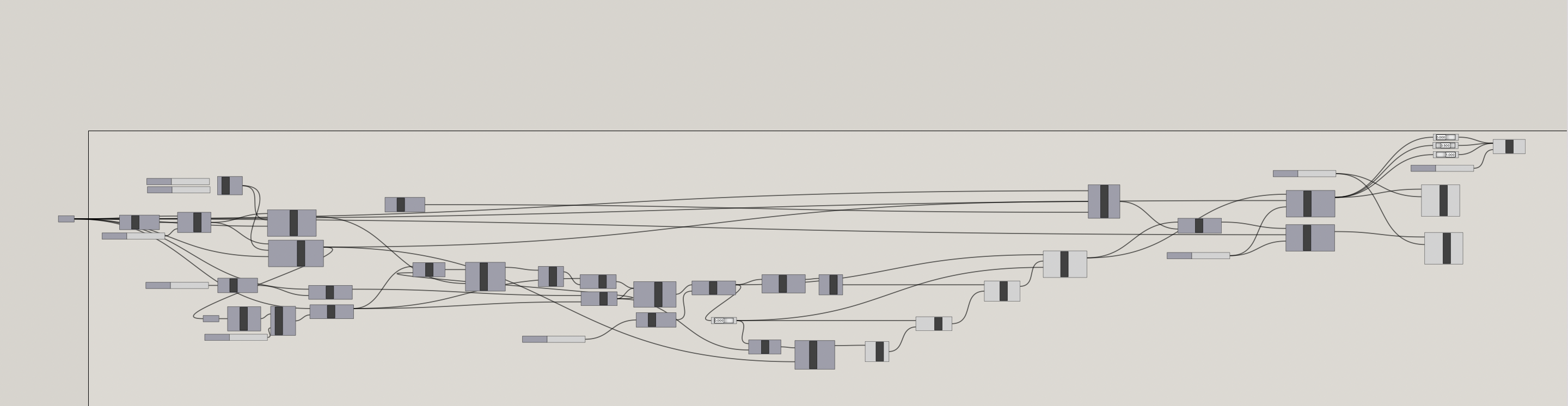
The first step was designing and fabricating a Hoberman circle. I began in Rhino by following a tutorial on Hoberman linkages and was successfully able to model the entire expanding circle in Rhino. Despite following a tutorial, the process of modeling this mechanism was challenging because the tutorial moved super fast, which meant that I had to keep pausing and rewinding. In the end though, the design was worth it, and I was able to create this parametric design:
After I laser cut all 24 pieces, I thought the hard part was over but boy, was I wrong. The first major hurdle came in connecting all the pieces together. It took me a while to screw all 48 3m screws and nuts into place and at first everything seemed fine. Yay! But, I realized things were going awry after I tried to transport the linkages from the SEC to the science center and pretty much everything fell apart. So, I redid all the screws and tried to add a locknut on top of the nut.
Thinking that I was done with the actual linkages, I set to work on the motor system. I knew I would have to design a stick-like thing that would be attached to the spinning motor and that to one of the linkages (so when the motor was spinning, the straight stick would push and pull the circle in and out, turning rotational motion into linear motion). I started by sizing up the spinning motor with calipers and then, using Rhino, I worked out my first stick design. It was basically a rectangle with a notch at one end to hook it to the motor and a small hole at the other to string a wire through, attaching it to the linkage. I decided to laser cut this design out of cardboard. The hole was a bit too snug, but since it was just cardboard, I managed to loosen it up to fit the motor! I fixed a wire to the other end, but it wasn’t sturdy enough to move the linkages. I swapped it out for a stronger wire, but it was too heavy for the cardboard to support. So, it was time to switch the material! I laser cut the piece from acrylic, which, unlike cardboard, isn’t as forgiving. It took a couple of tries to get the dimensions just right for the motor to fit snugly into the acrylic hole. After attaching everything – stick to motor, wire to stick, and wire to the circle linkages – it was time for the moment of truth. I flipped the switch, but nothing worked! The motor was just wobbling about, lacking the proper support. During this whole ordeal, the circle got jostled around, and screws and bolts were dropping like flies. It was pretty frustrating, to say the least. I figured out that I’d put the locknuts on wrong – they were supposed to replace the nuts, not complement them. After taking a break and grabbing a brownie, I returned and reworked all 48 screws, this time just using the locknut. My hands were aching by the time I finished, only to realize, after a chat with Nathan, that the screws were too short for the locknuts. So, back to the drawing board again, unscrewing and rescrewing all those screws with bolts on the ends. I dabbed on some hot glue to keep everything in place. It wasn’t perfect, but it was something. I decided to call it a day at that point.
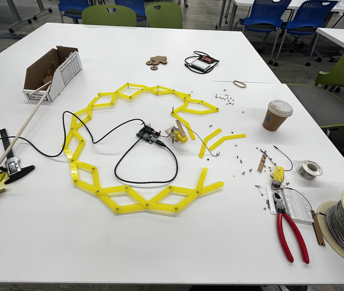
After a good night's sleep, I was excited to dive back into the project. I started by inspecting my circle; it was holding up well, and none of the bolts had come loose. Things were looking up! Next, I used MakerCase to design an enclosure for my motor and Arduino, and laser-cut it out of cardboard. I glued the motor body inside the top of the box, leaving only the moving part accessible through a hole in the cardboard. However, I soon realized that the design was flawed. The Hoberman circle and the motor needed to be on the same plane, but the box elevated the motor. So, I went back to the drawing board and redesigned the box top as a large circular disk where I could place the circle. The laser cutter had its limitations, so I couldn’t make the circle as large as I wanted, but it was good enough for a prototype. Next, I decided to revise my acrylic stick and wire setup due to difficulties in attaching the wire to the circle. I came up with a new design, completely crafted from acrylic, and secured it using m3 screws.
After assembling all the parts, it kind of came to life! Yay! However, there was a snag; the nuts on the circle joints were jamming at the edge of the cardboard, preventing the circle from expanding and contracting. To solve this, I used a larger piece of cardboard and cut out slots to align with the base of the box. This adjustment made things run more smoothly! But, the motor was still revving too quickly. To refine this, my plan is to develop a gear system to regulate the motor's speed. I also need to reinforce the support system; currently, the box’s small base and large top make it unstable. I’m really proud of the progress I've made this week and excited to continue refining my project in the coming week!